Clip from one of our Cold Flows
Liquid Rocketry Lab (LRL) is a 501(c)(3) non-profit company comprised of 150+ NCSU students. As one of North Carolina's premiere liquid propulsion and launch vehicle research teams, we're racing to build the first collegiate liquid-powered rocket to reach the Karman line: the edge of space. Additionally, we've designed and built a large mobile test stand, paving the way for a sustainable propulsion program at NC State.
I joined LRL in the fall of 2023 as a freshman and got involved in the propulsion team, working with subteams like Test Operations and Catalyst Bed. Over the next year my main focus was the catalyst bed team, where I took part in researching catalyst beds, and how we could design one for our engine. During the research phase I learned a lot from more experienced members like our team lead, and was able to work closely wih the team on designing the catalyst bed for Argenta 7A, our engine. We spent a lot of time on the design, as we wanted to make sure it was efficient, affordable, and reusable. The team went through countless design iterations as we discovered new papers and new ideas for optimizing the engine, and thus the catalyst bed.
At the end of 2024, I was promoted to Principal Engineer of the Catalyst Bed team. Here I manage 9 people across two subteams (Catbed Housing Manufacturing & Catbed Electroplating). Since then, I have been leading the design, valiation, manufacturing, and soon testing of the Catalyst Bed. My main focus has been leading the manufacturing of the catalyst bed, and have been making decisions based on cost, time, and quality. Along with manufacturing comes leading new design modifications, requiring in depth documentation, validation through ANSYS, manufacturing planning.
This experience has been immense for me. I have developed my skills in engineering leadership, with skills like project documentation, managing two subteams, along with setting and meeting PDR and CDR deadlines. I have also developed my skills in engineering design, manufacturing processes, ANSYS simulations, and more technical skills detailed below.
Starting in the summer of 2025, I took on the role of Propulsion Team Lead. I’ve been leading the propulsion team in preparation for our upcoming hot fire test, coordinating technical efforts across multiple sub-teams to ensure readiness. To reduce knowledge bottlenecks, I’ve worked to distribute critical tasks beyond Principal Engineers, helping maintain project momentum during exam periods and other academic demands. I’ve also improved team retention by organizing regular team-building activities and promoting more equitable work distribution, giving every member ownership of meaningful projects. In collaboration with Principal Engineers, I’ve supported mentoring efforts and helped balance workloads across the team. Additionally, I’ve focused on building a sustainable team structure that accommodates student schedules while maintaining steady technical progress.
The Argenta 7A is LRL's ~31kN bipropellant engine. Argenta 7A is designed to generate experimental data for developing flight-ready rocket engines (future versions will follow as revisions B, C, D, etc.). This design prioritizes manufacturability, simplicity, and quick production for testing purposes. A pressure-fed, bi-propellant engine using HTP & Jet A as propellants was chosen.
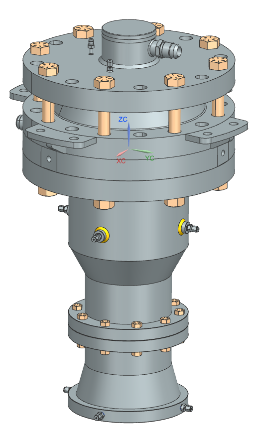
Argenta7A CAD
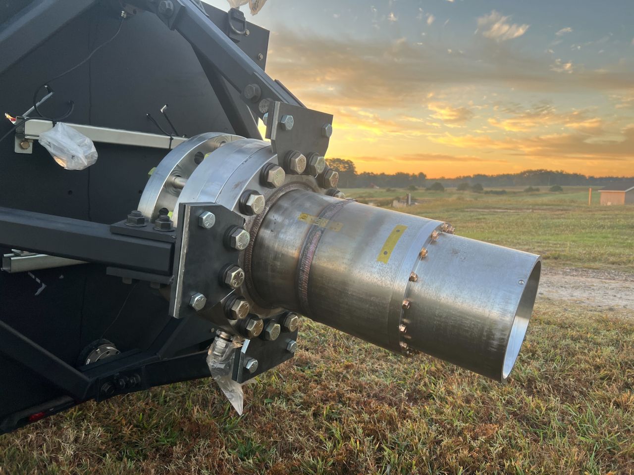
Assembled Aregnta7A
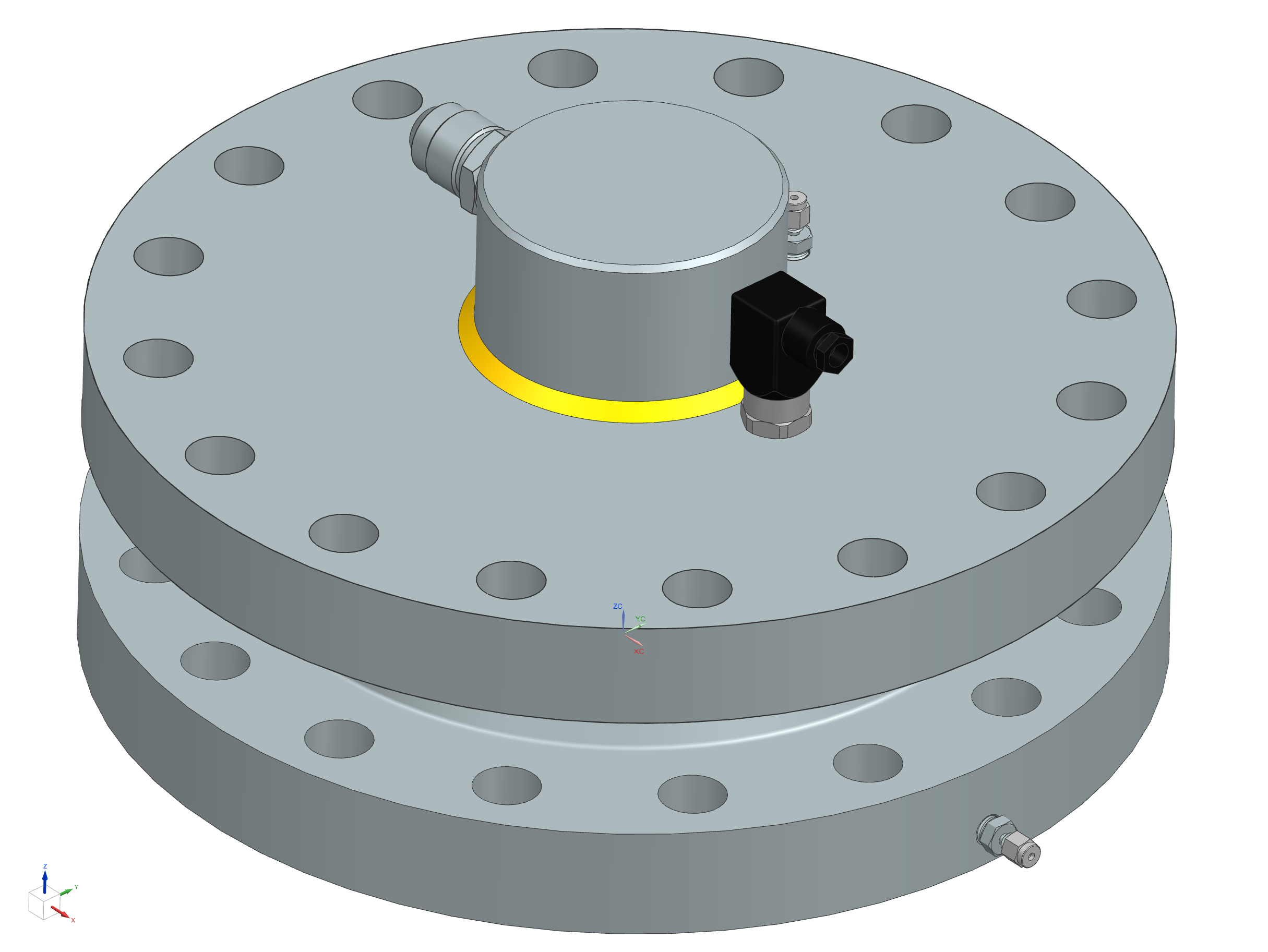
The Catalyst Bed
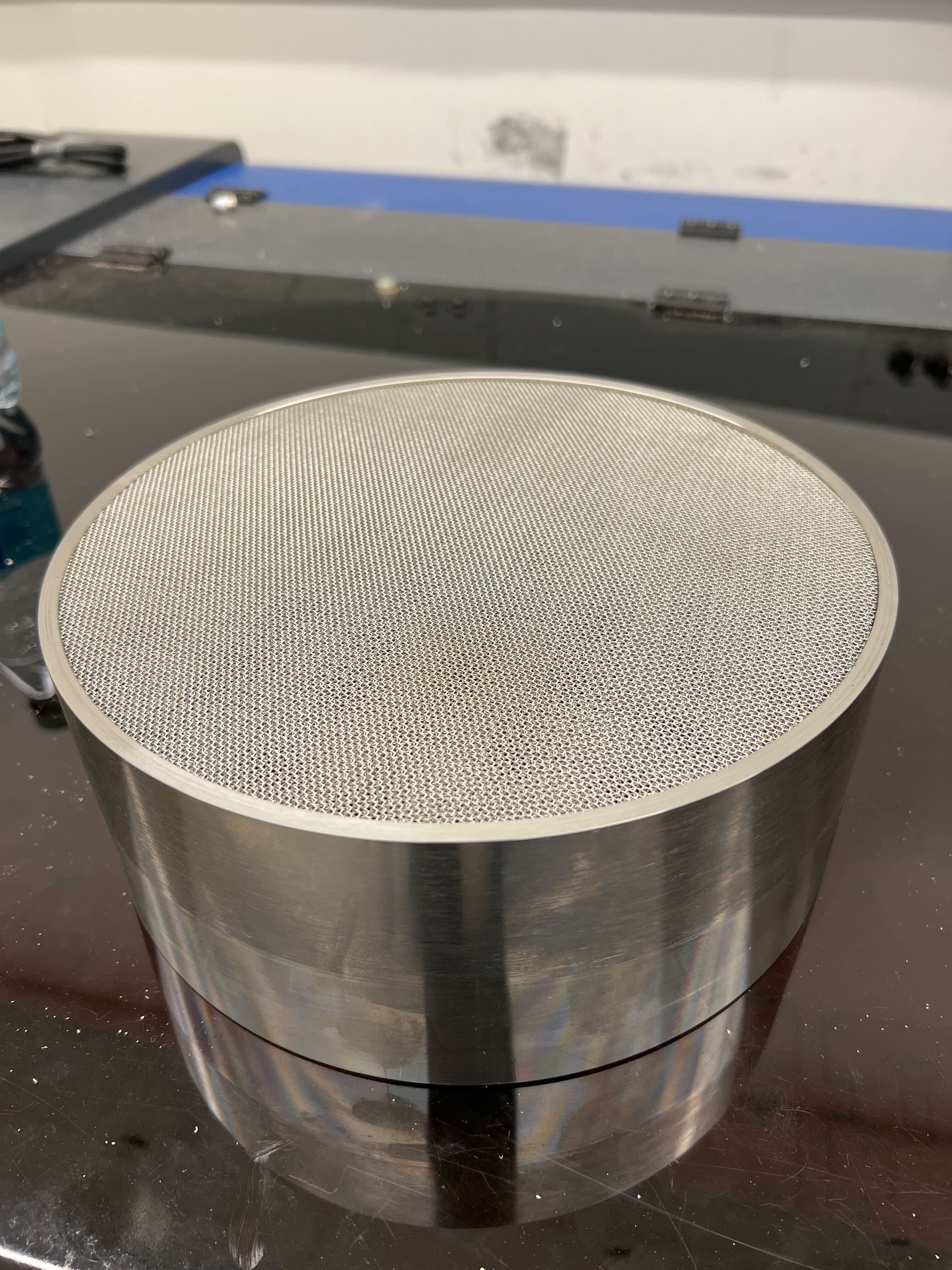
Our catalyst bed is a large silver mesh catalyst bed that will decompose 11 kg/s of 90% HTP, which will be part of the 31 kN HTP/JetA bipropellant engine.
A catalyst bed is used to decompose a propellant, in our case 90% HTP or High-Test (Hydrogen) Peroxide, into products that are more readily combustible with JetA. Additionally (and crucially), the decomposition reaction releases a significant amount of energy in the form of heat and kinetic energy (rapid gas expansion). HTP decomposes into primarily superheated steam and gaseous oxygen. These decomposition products are then injected into the combustion chamber. They flow through the gas ports of the injector where they are mixed with JetA. The decomposition temperature of 90% HTP is approximately 1000 K, which is high enough to auto-ignite JetA with gaseous oxygen. A well understood catalyst type used for HTP are stacked silver screens. This is the catalyst type that we pursued for our design.
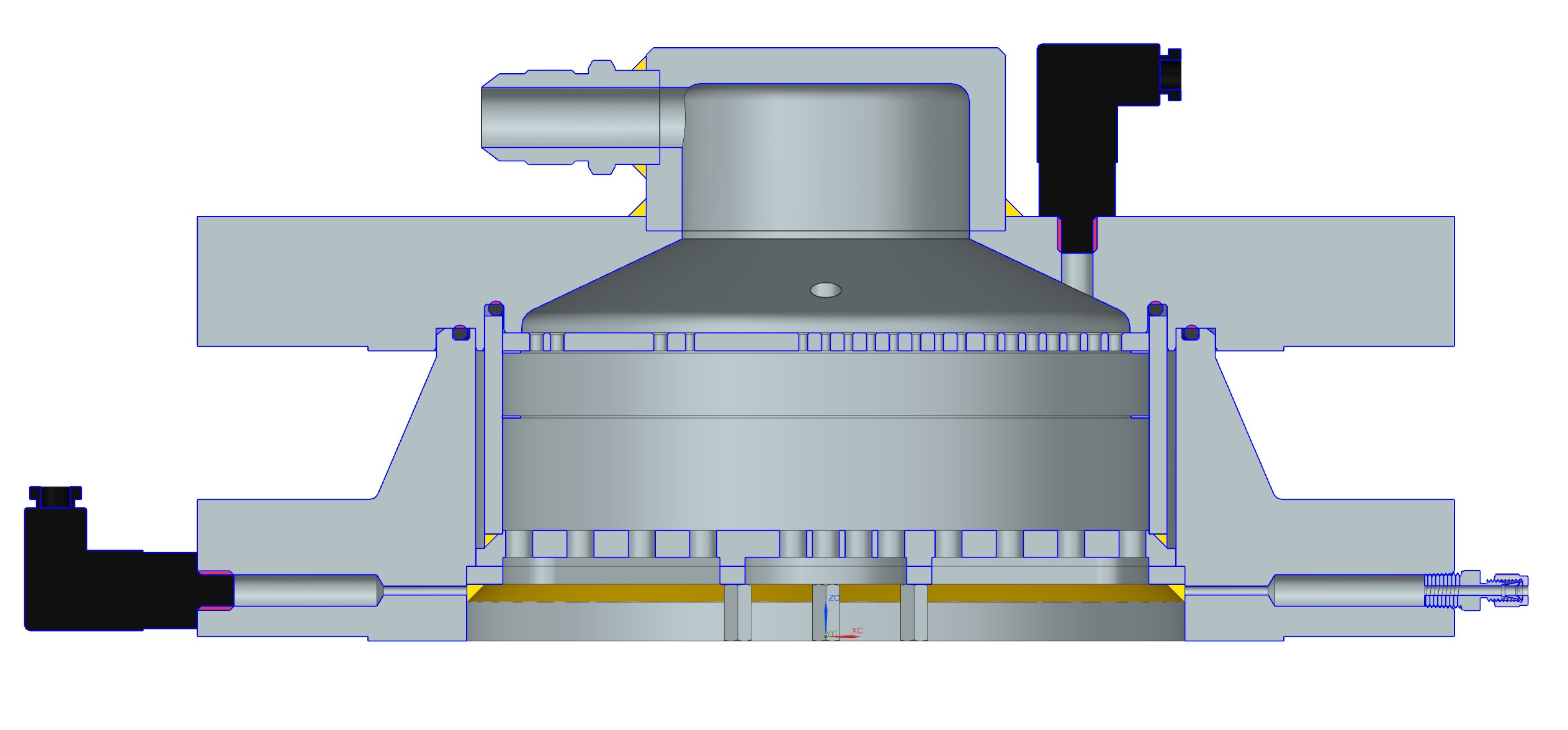
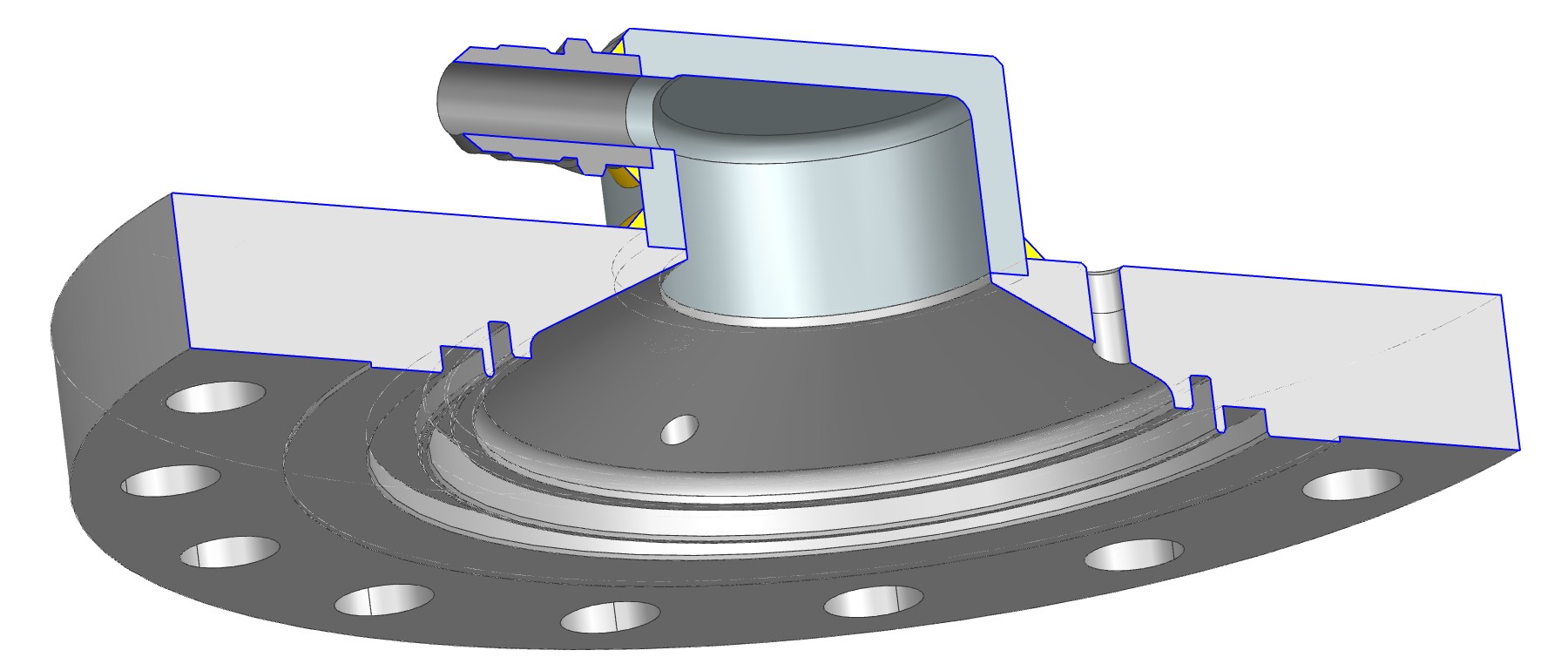
CatBed Section View
During my time as a member of the Catalyst Bed team, I worked closely with the previous team lead to learn as much as we could about Catalyst Beds, and to
help with this design process. The bed consists of the housing and catalyst cartidge. Made of 304 stainless steel, the housing is designed from two flanges
which will contain the silver mesh stack.
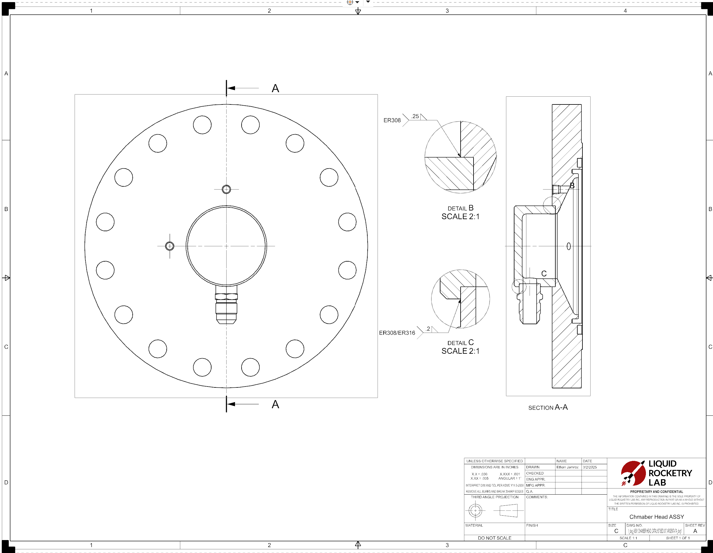
Chamber Head - Main component that directs flow
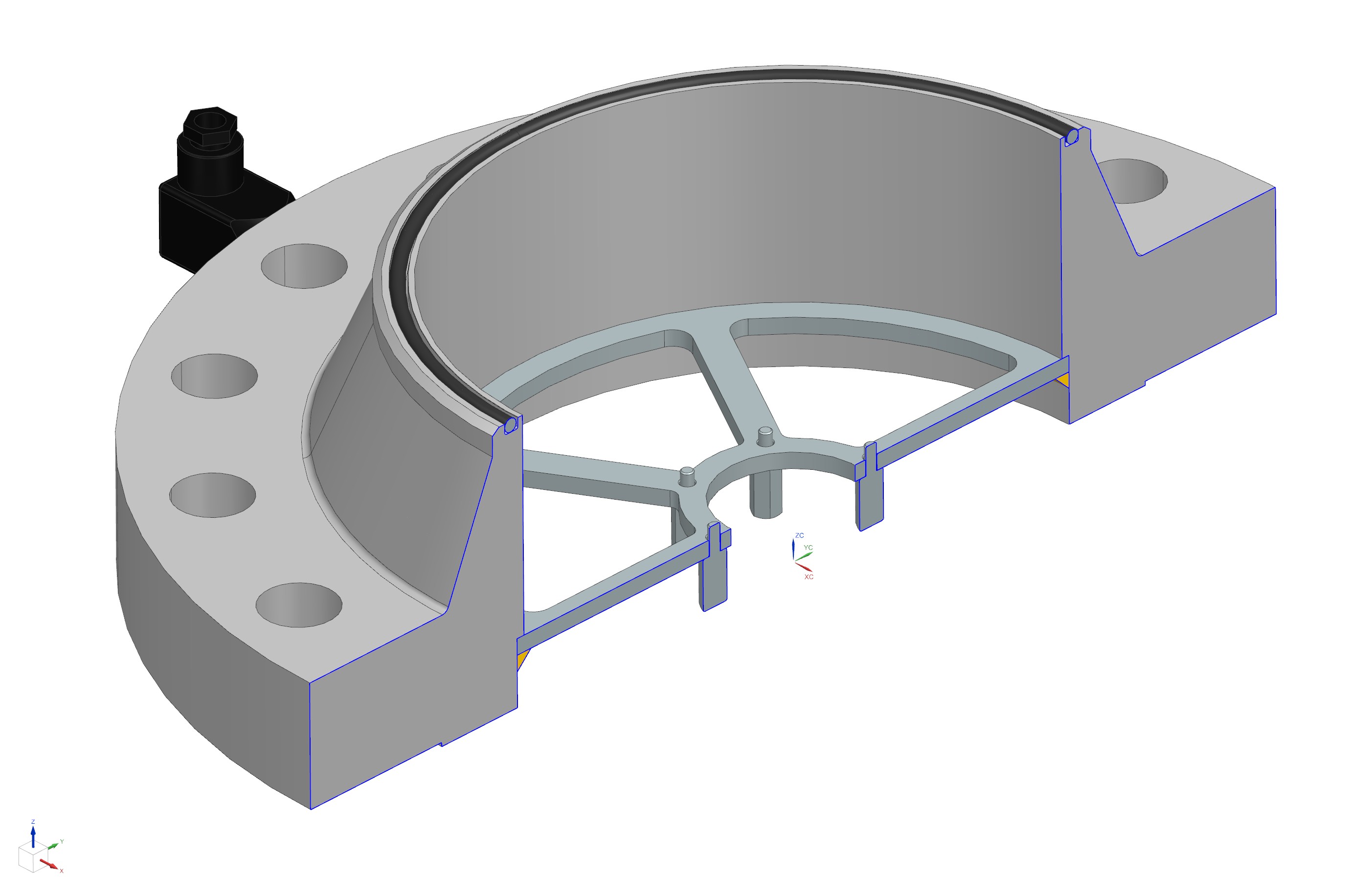
Chamber Housing - Contains the catalyst material
Catalyst Cartridge - Replaceable element
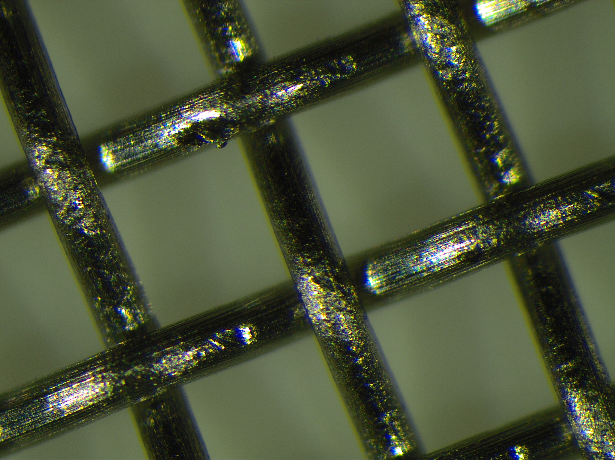
Unplated SS Mesh (~100X mag)

Nickel Struck Mesh (~100X mag)
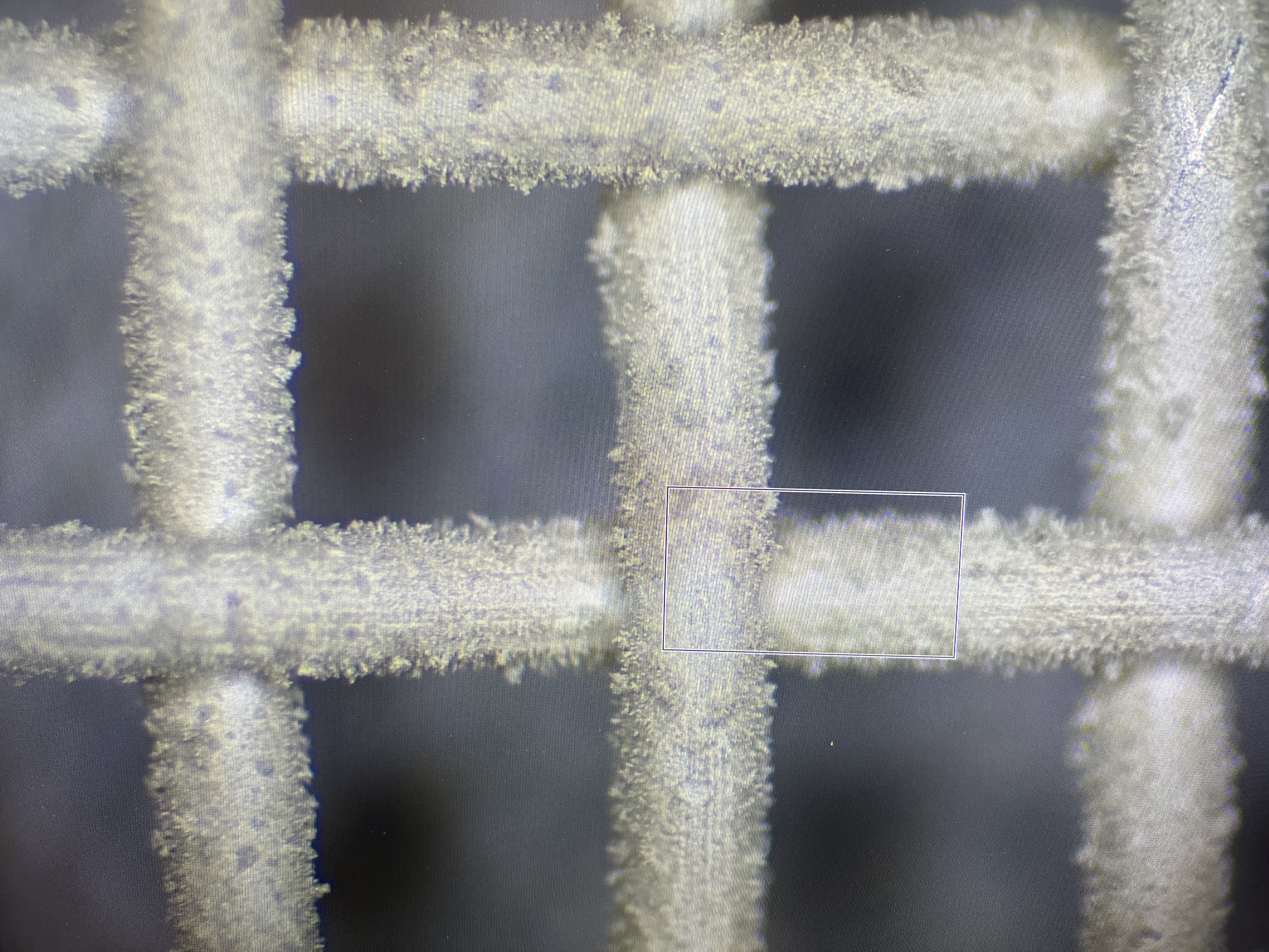
Silver Plated Mesh (~100X mag)
During the 2024 summer, I led the research and procedure writing for the electroplating of the silver mesh. This was a crucial step in the design process, as we quickly discovered purchasing a silver mesh was unaffordable. We decided to electroplate the mesh ourselves, which is a lengthy process. After a lot of reading about a few different methods of silver plating, I decided we'd go with a cyanide based silver plating solution. This process has its pros and cons, but it was the best option for our application.
When we look at the positives, the cyanide process is the most effective silver plating method, with dozens of years of use across a dozen industries.
The cyanide process is also known to have the best adhesion, plating surface controlability, and the best conductivity.
The negatives are that the cyanide process is the most dangerous, and requires a lot of safety precautions. This means I had to go into a deep dive on cyanide safety, and what the concerns actually are here. This involved drawing up safety procedures that we eventually cleared with Environmental Health and Safety at NC State (EHS).
Our plating process is a 3 step plate which goes on a stainless steel mesh. It involves a nickel strike, a silver strike, and a silver plate, with thicknesses that follow aerospace standards for plated catalysts.
We are currently in the plating proccess and have just finished several rounds of nickel striked plating. To the right are some images of the plates under a microscope. At this time I am waiting on respirator fittings with the EHS department so I can start the cyanide based silver process.
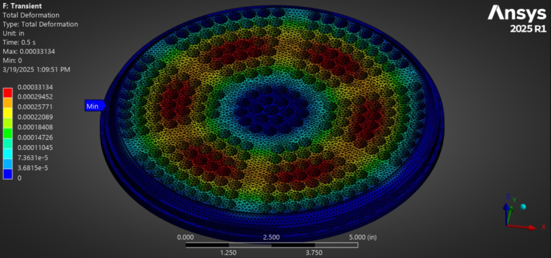
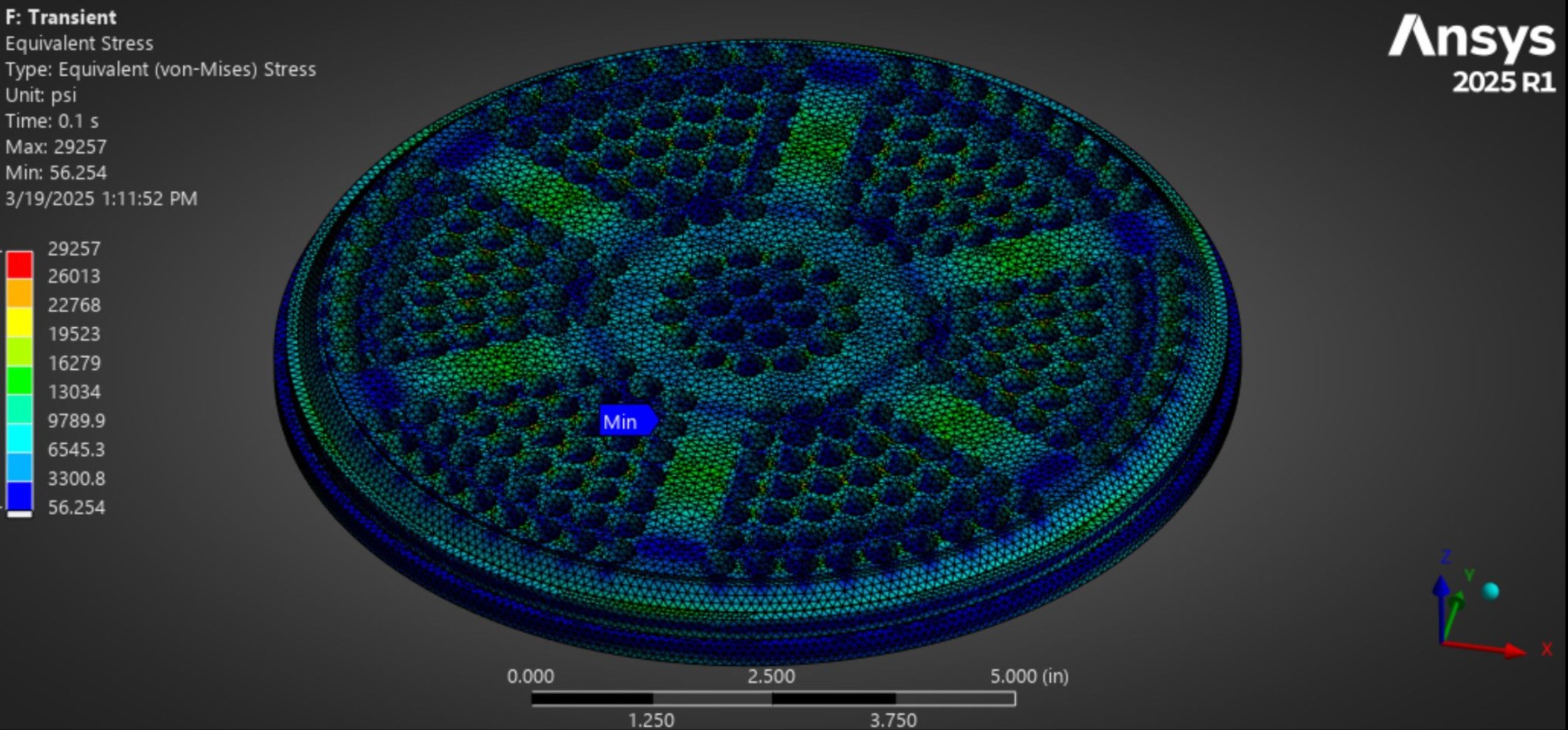
Validation has been a huge part of the process on the way to a critical design review. The previous team lead and I have sunk countless hours into the validation of the catalyst bed to ensure safety and efficiency. As it is a high pressure & high temperature vessel that is essential to downstream components, we have to make sure it is safe and reliable. The things we have to consider are steady state and transient pressure analysis (1,2), transient thermal analysis (3), bolt pretensioning and it's effect on the sealing of the flanges (4,5,6), and more. It's been a really great learning opportunity for me, as before this, I had only classroom Ansys experience.
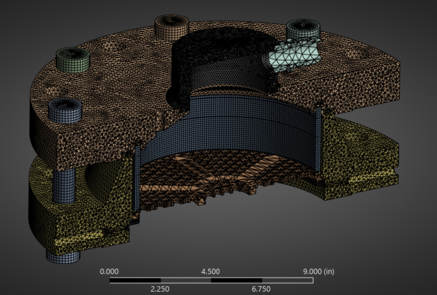
Medium Density Meshing (1)

Bolt Pretension Test Setup (2)
Transient Thermal Temp Results (3)
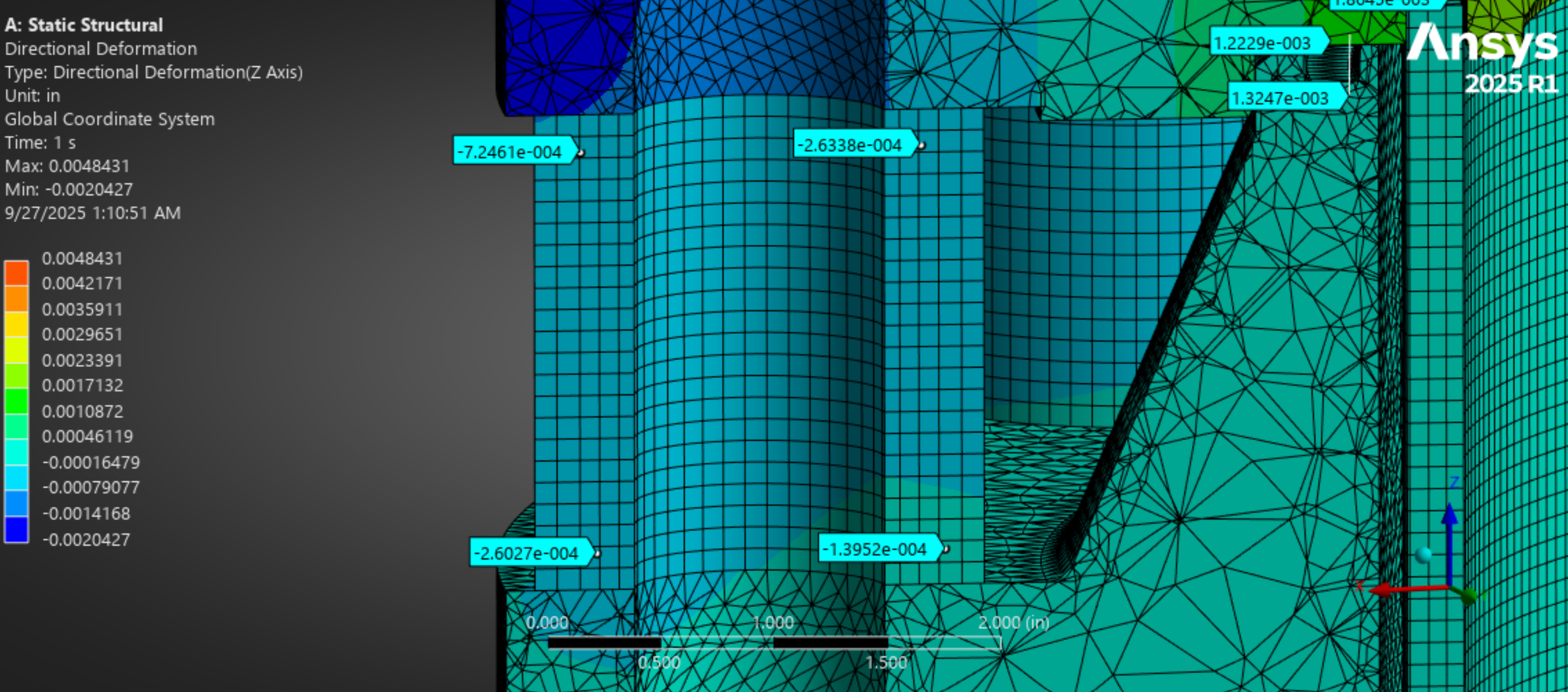
Flange Spacer Deformation (4)
15k lbf seal deformation (5)
30k lbf seal deformation (6)
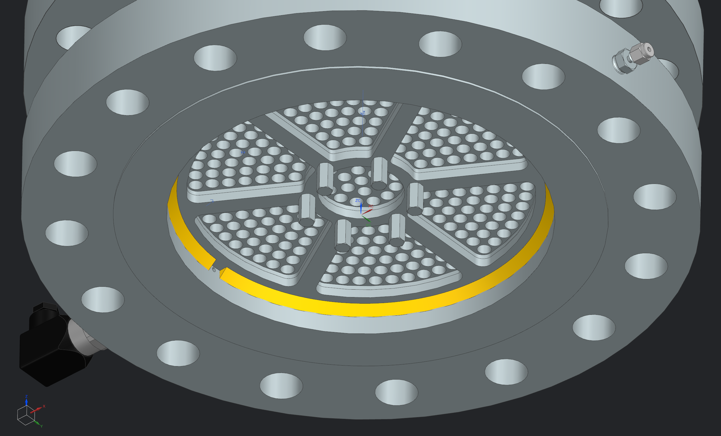
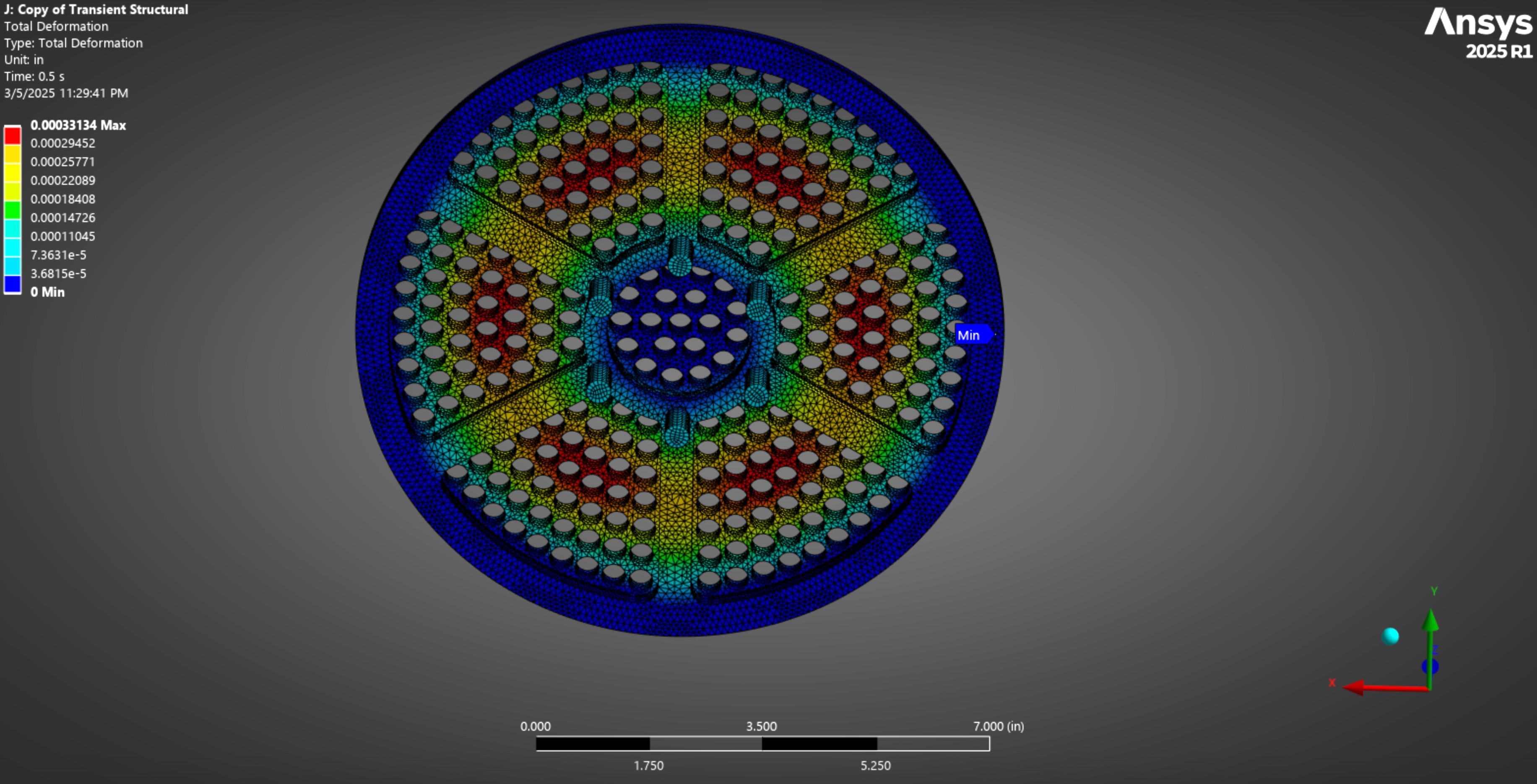
One of the biggest design challenges I had to overcome was the structural integrity of our support plate. The support plate the bottom part of the Catalyst Cartridge, and supports the mesh stack (Fig 1 Below). Something I noticed while validating our original design was that the plate could not handle the startup pressures of the Catalyst bed.
In steady state operation, the upstream pressure (in the cartride) is ~650 psi, while the downstream gas pressure is ~575 psi due to pressure drop. This results in a small pressure differential which has minor stresses on the plate.
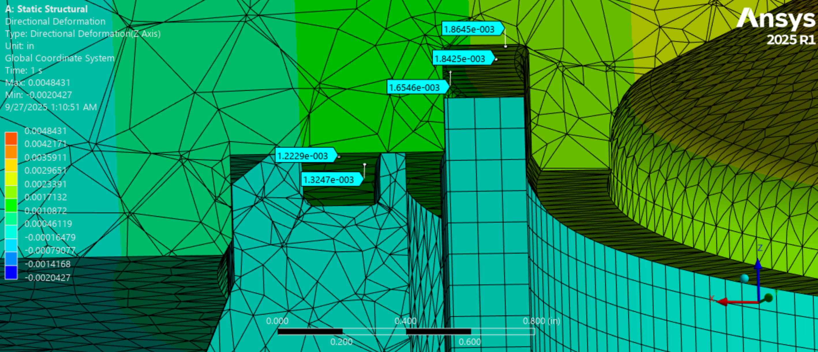
More importantly is Catbed startup, where the upstream pressure is ~650 psi before the downstream has ramped up. This results in a large pressure differential which we saw cause yielding in multiple parts of the plate (Fig 2&3 Below).
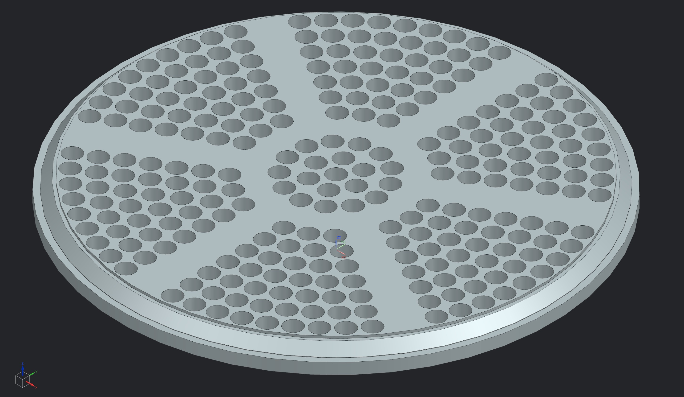
(1) Support Plate
(2) Original Design Yielding Under Transient Loading
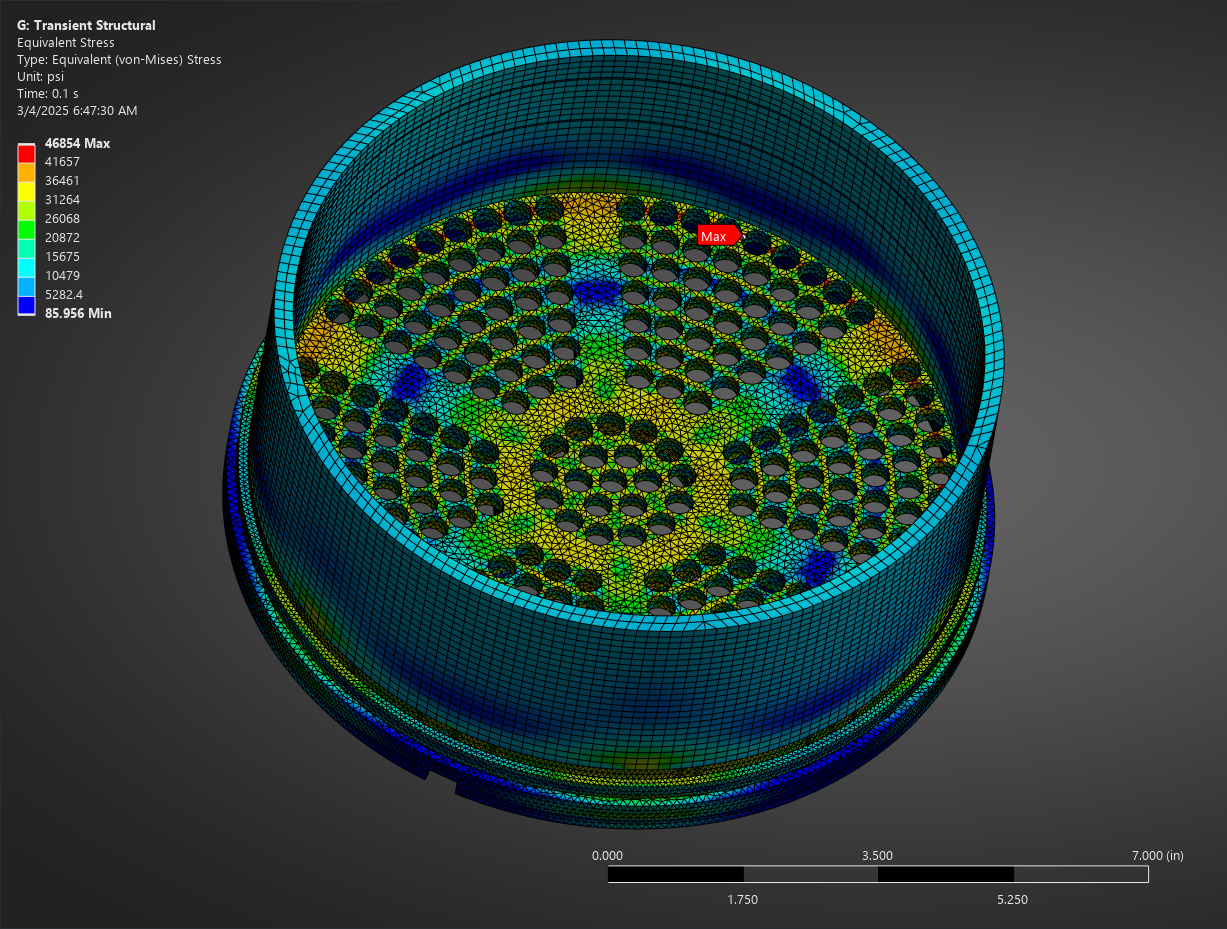
(3) Original Design Yielding Under Transient Loading 2
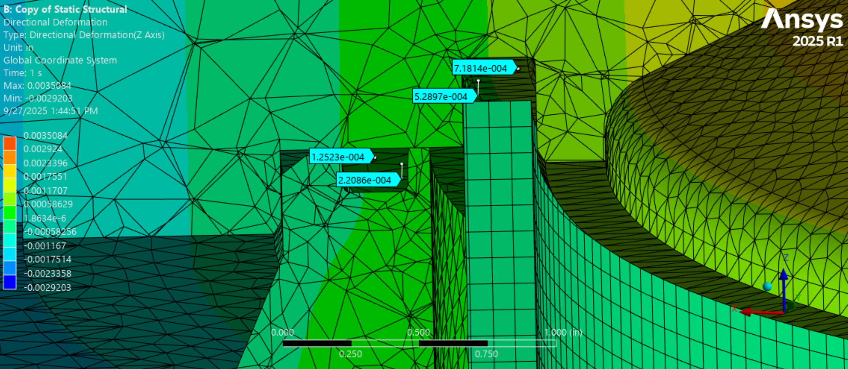
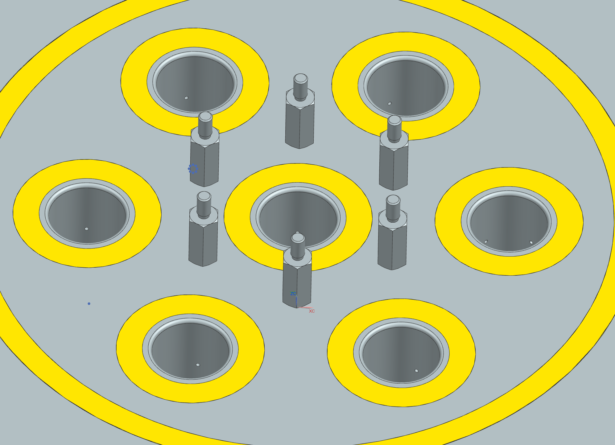
To solve the issue with yielding and deformation upon catbed startup, I had to go through a few design iterations on the support plate. There are a few adjustments that helped, but the biggest was including threaded standoffs into the bottom of the plate (Fig 1&2 Below). These standoffs sit on the injector face downstream (Fig 3 Below) to stop the plate from deforming in the center.
This design has been validated through Ansys, and has shown to be a lot more effective than the original design. Although this was a setback in my timeline, I'm glad it happened before manufacturing, as it would have been a lot more costly to fix after the fact.
(1) New Support Plate
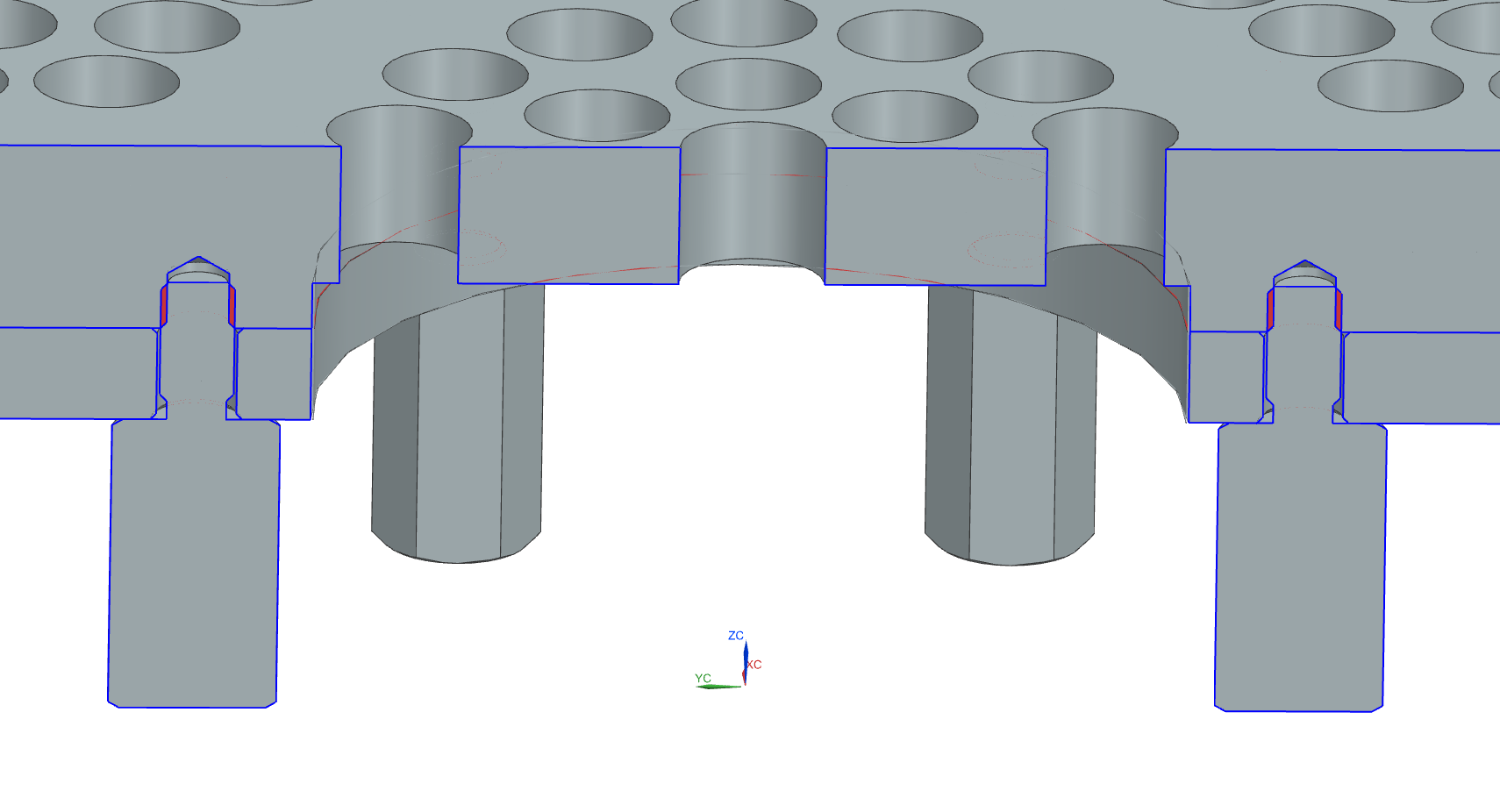
(2) Support Plate Cross Section
(3) New Support Plate Welded
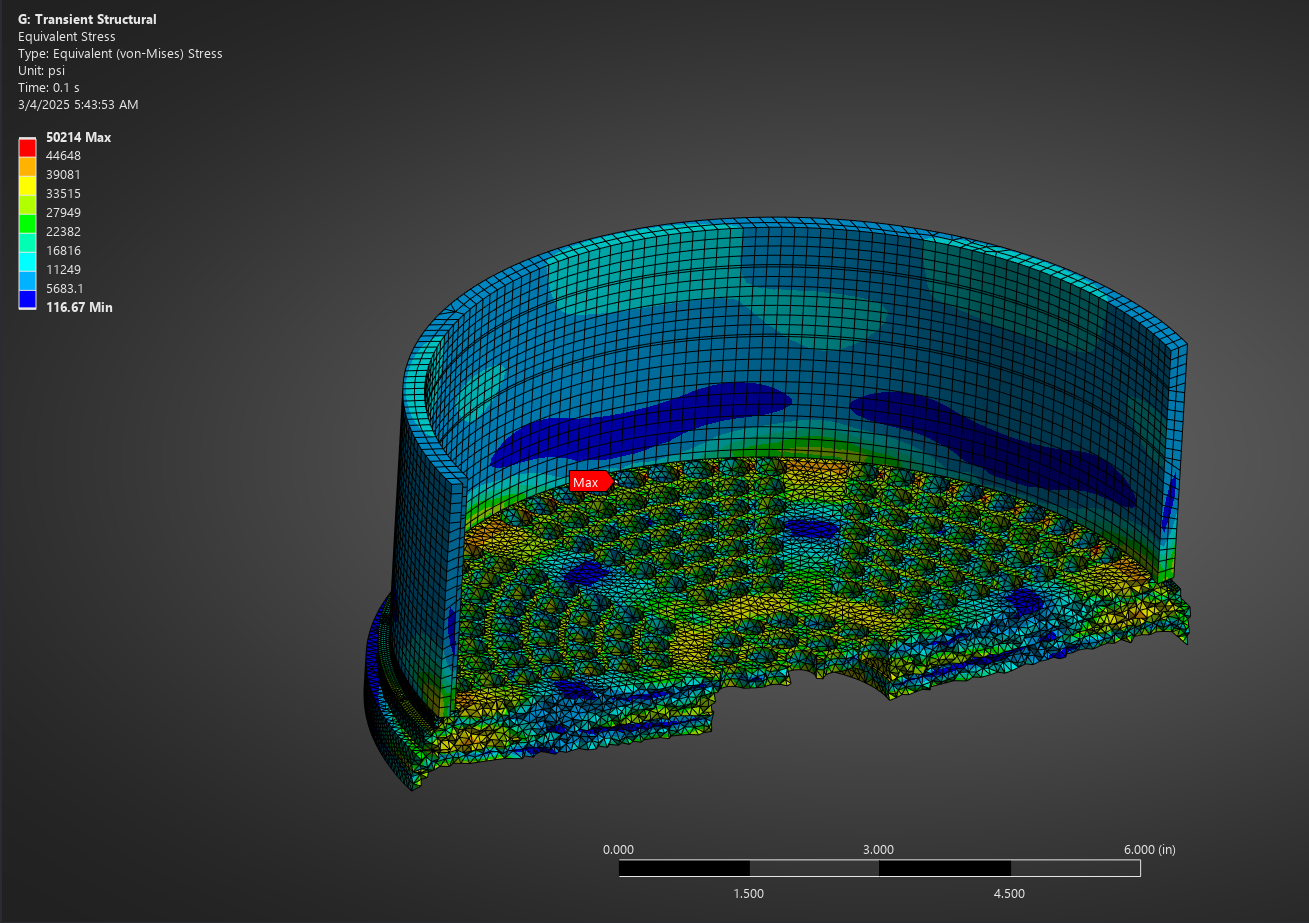
Eq. Stress at 700K
Yield ISO at 700K
Yield ISO at 800K
So much Validation needs to be done at LRL, as with the budgets we work with we can't afford to make mistakes. There are way more validation sims than shown on this page, but it would be impractical to show them all.
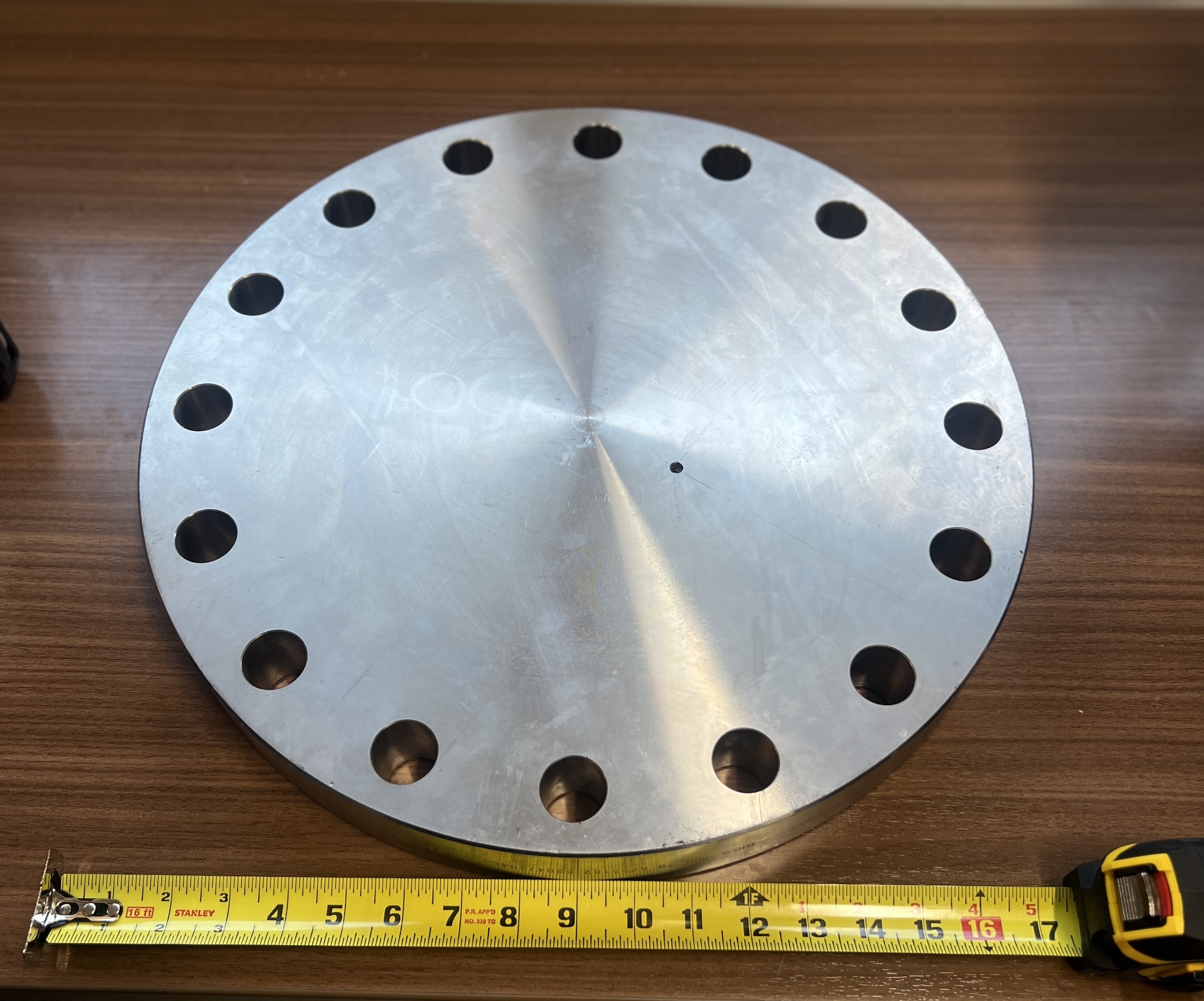
Blind Flange - Pre-Mfg
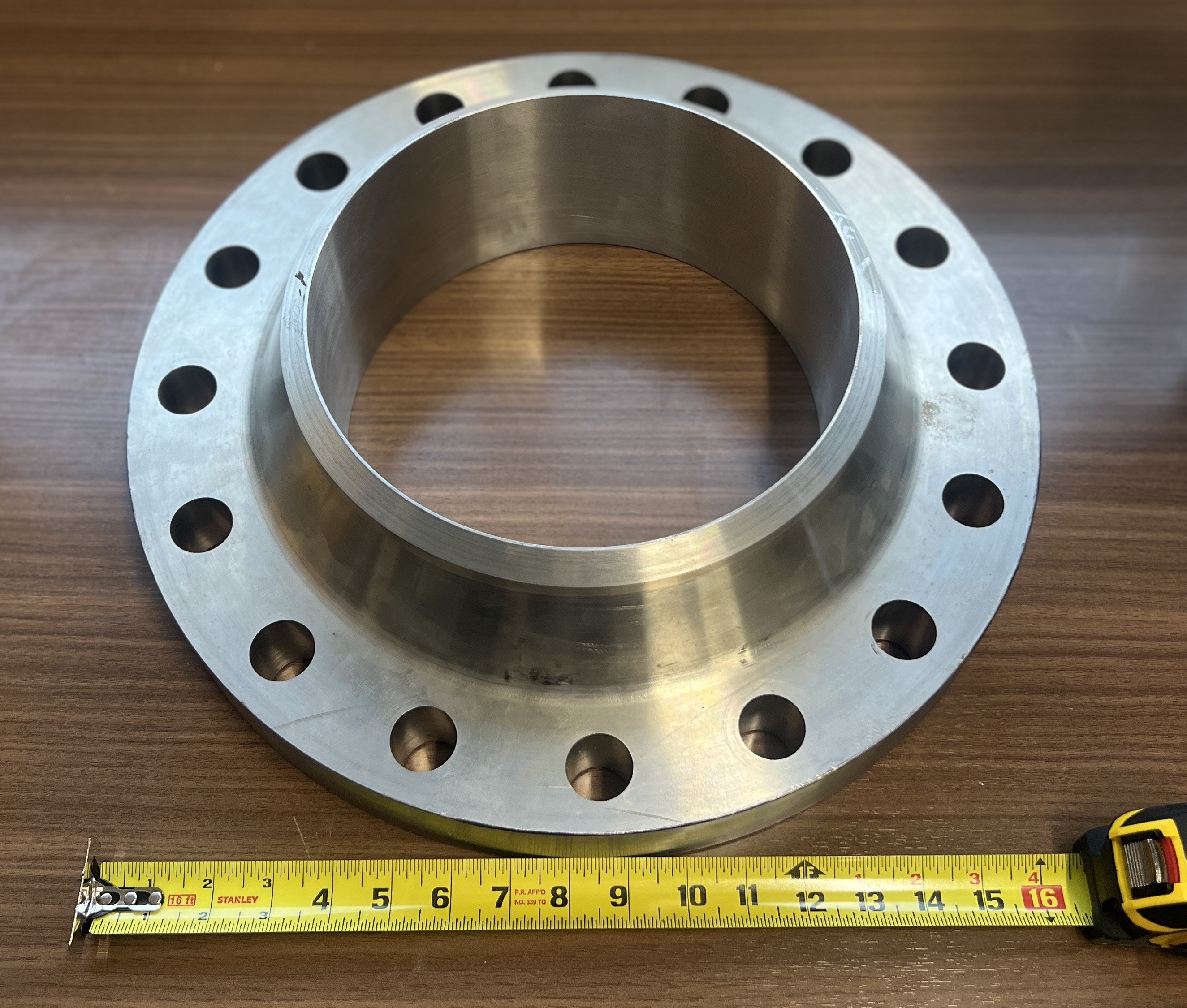
Weld Neck Flange - Pre-Mfg
By far my biggest responsibility as the Principal Engineer of the Catalyst Bed team has been leading the manufacturing of the catalyst bed housing. Mainly made of 304 stainless steel, the catalyst bed housing consists of 3 main assemblies. The chamber head is made from a class 300 ANSI B16.5 blind flange that I will mill on a CNC machine. Similarly, the chamber housing is made from a class 300 ANSI B16.5 weld neck flange that I will mill on a CNC machine.
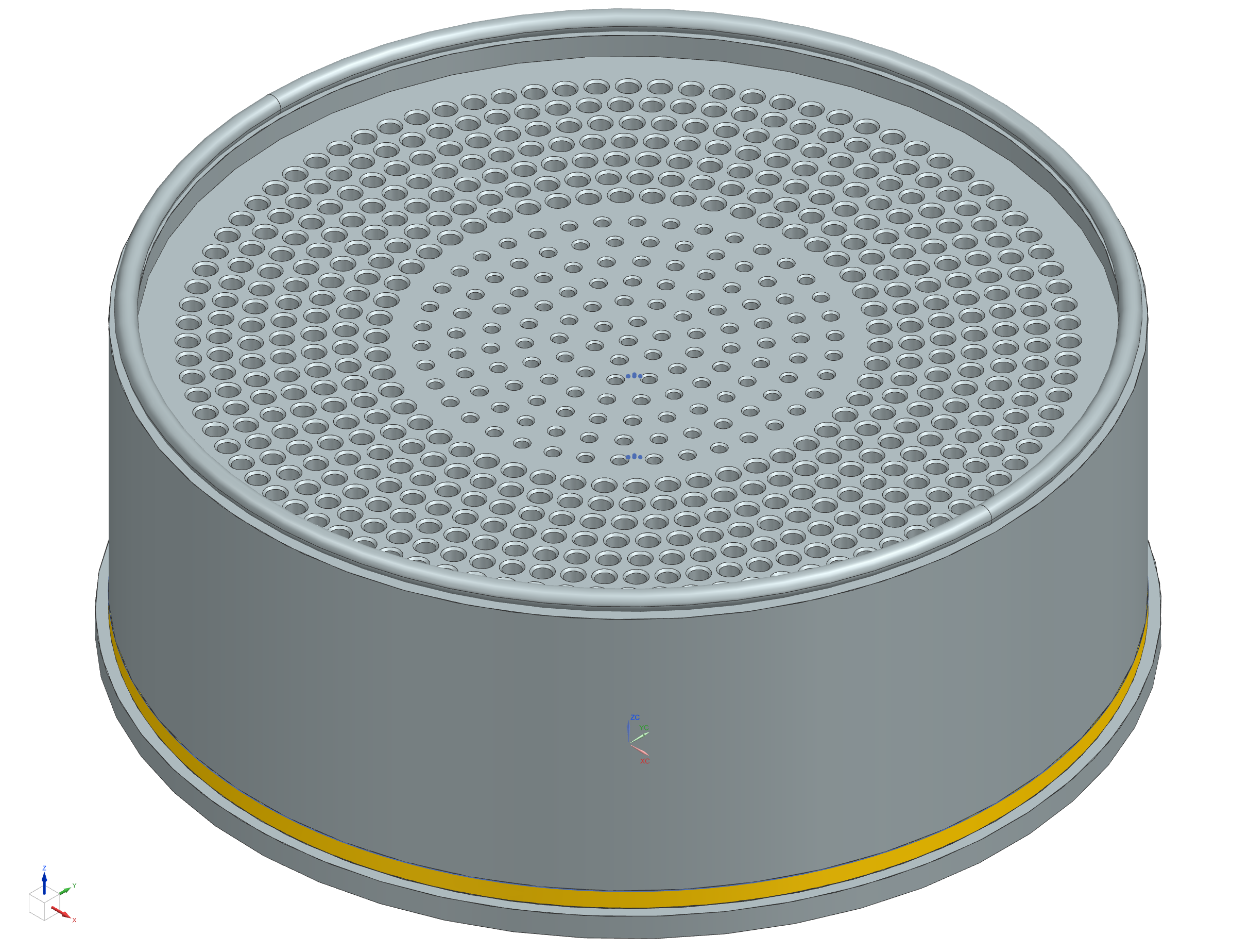
The cartridge is a bit more complex, as it is made from a 304 stainless steel tube that I will have touch up on a lathe. The tube is then welded to the support plated which is what helps support the pressure of the catalyst chamber while still providing distibution without pressure drop. The meshes are then compressed inside the tube at around 1000 psi, and on top is placed the distribution plate. Then the cartridge would be dropped into the chamber housing and blted shut.
The prep for the manufacturing process has involved using NX to create the MFG drawings for each part, picking how each feature will be created, finding end mills and other tools needed, and learning how to use the CNC machine. I also had to focus on cost and time, as we are on a tight budget and schedule. I should have this entire bed manufactured for less than a thousand dollars, and with certain partners and sponsers I've reached out too it could get cheaper as well. Below is a collection of a manufacturing drawings that I made for the parts.
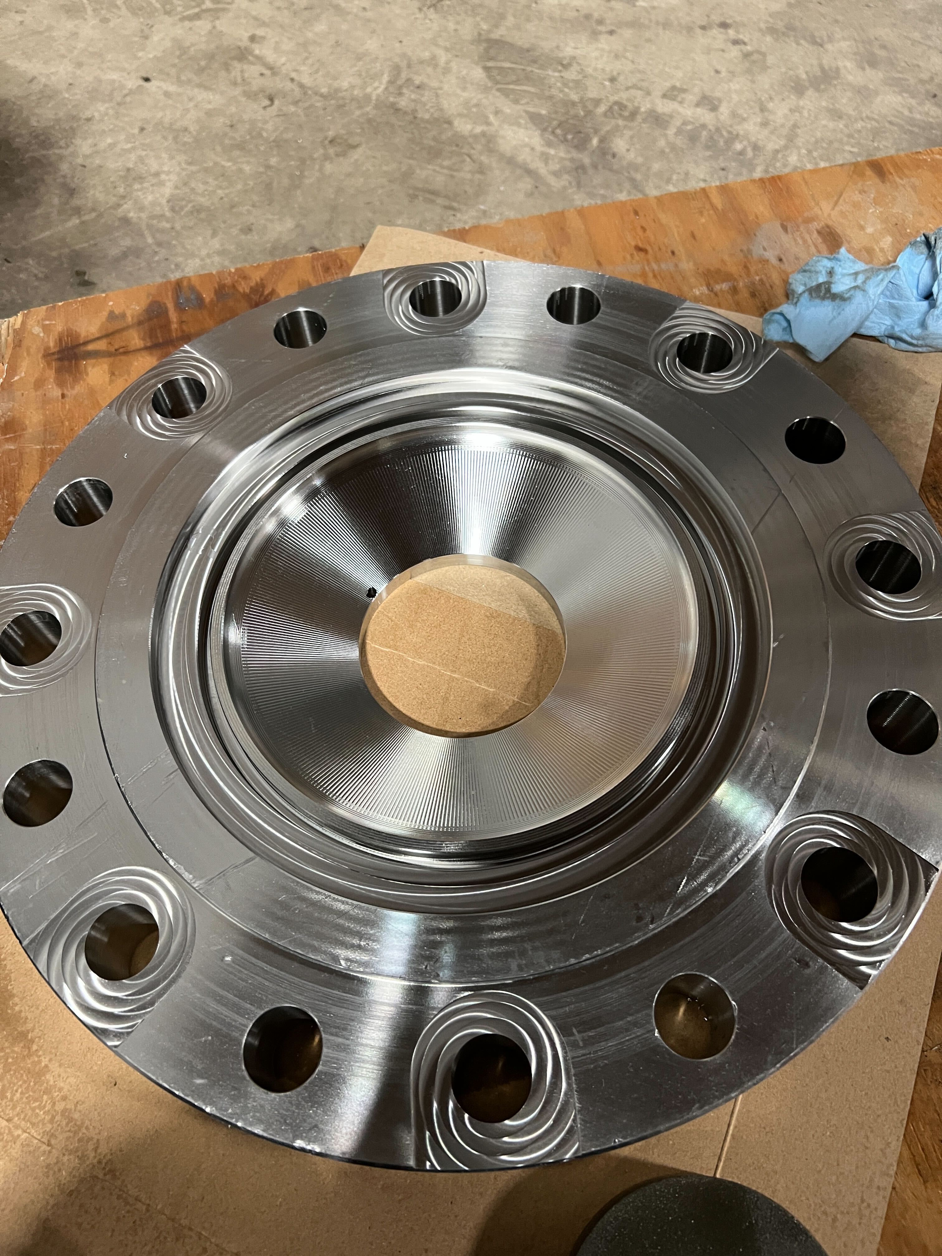
Catbed Housing MFG
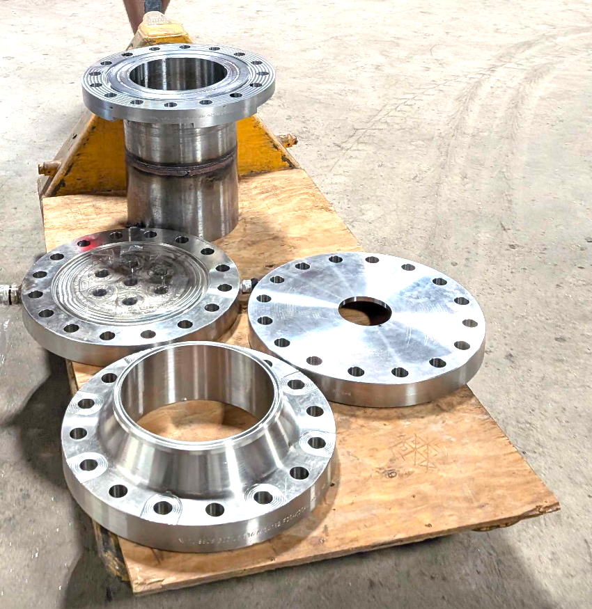
Parts leaving the mill
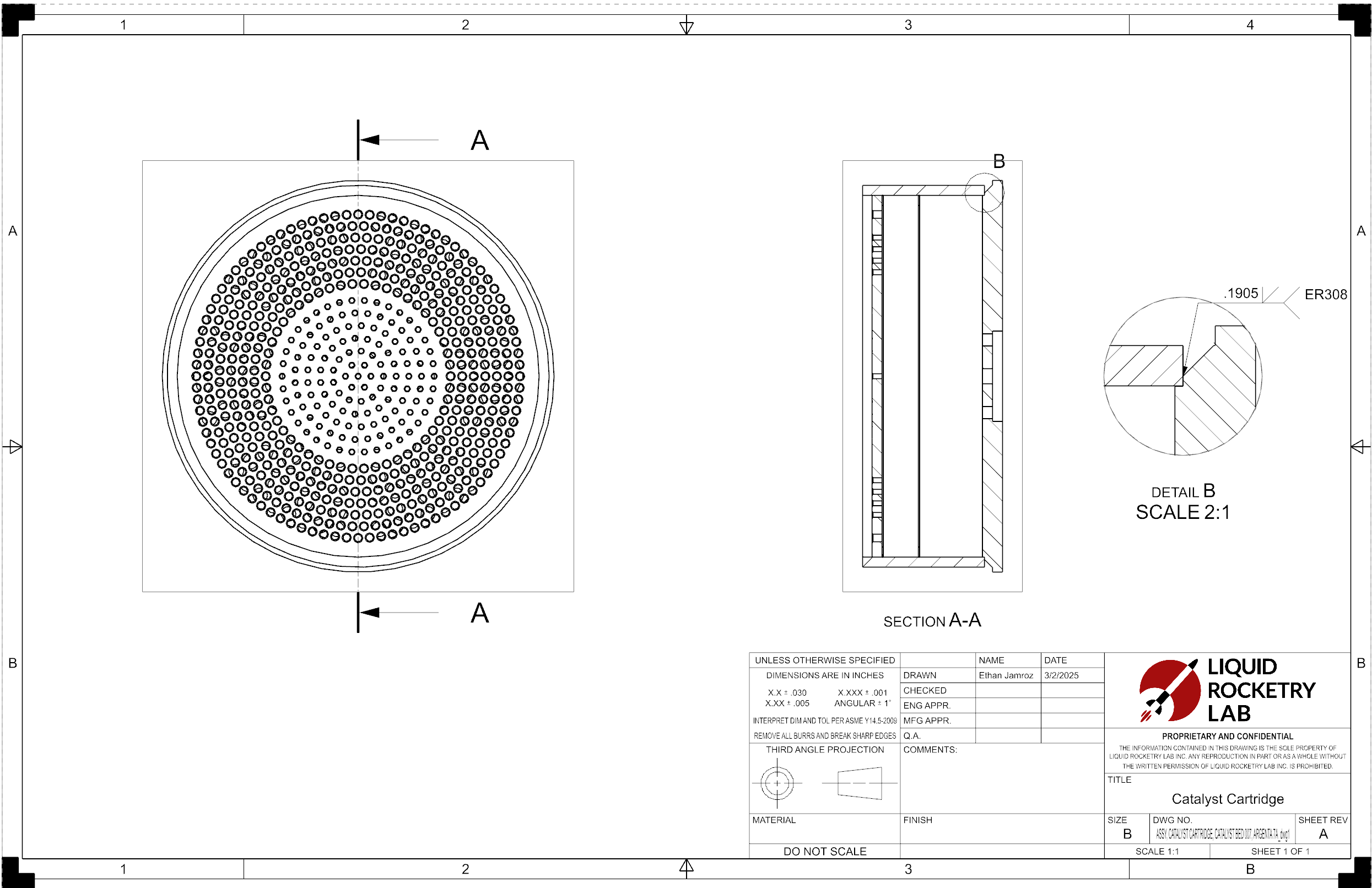
Catalyst Cartridge

Chamber Head Pipe DWG
Chamber Head Flange DWG
Chamber Housing Flange DWG
Distribution Plate DWG
Support Plate DWG
Head Assembly DWG
Cartridge Assembly DWG

Housing Assembly DWG
This project is ongoing, and is about to be manufactured. I will update this page with the results of the manufacturing process. After that will come testing!